Wiring 15A Switched Socket Outlet [15A Receptacle]
" The experimental investigation by which Ampere established the law of the mechanical action between electric currents is one of the most brilliant achievements in science. The whole theory and experiment, seems as if it had leaped, full grown and full armed, from the brain of the 'Newton of Electricity'. It is perfect in form, and unassailable in accuracy, and it is summed up in a formula from which all the phenomena may be deduced, and which must always remain the cardinal formula of electro-dynamics. "
Wiring 15A Switched Socket Outlets [15A Receptacles]
Wiring of 15A Switched Socket outlet point is very much in need in Electrical Installation Work.
Here we are considering wiring a 15A Socket Outlet [Receptacle] point for 50Hz, 230V AC Power Supply. Installation work described here is according to British Standards. [IEE Regulations and Practice ].Material Requirement
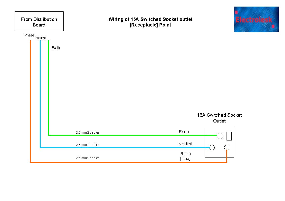
For Industrial or Residential applications, 2.5 mm2 [called as 2.5 mm squared] Cross sectioned double insulated Cu [Copper] Cables [Cu/PVC/PVC] are used for the Phase [Live ] and the Neutral cables.
Earth [Ground ]cable should be 2.5mm2 single insulated Cu[Copper] Cables [Cu/PVC] for both Industrial or Residential type of applications. Cable lengths for the above circuits will be such that voltage drop along the cables will be with in the approved limits of 10% of Supply Voltage.Accessory Requirement
PVC Box to install the 15A Switched Socket outlet-01 nos
15A Switched Socket outlet-01 nos MCB 16A -01 nos [ from a Distribution Board already installed]Preparation
Install the socket outlet box at the required position.
Lay 3/4" PVC conduit from the Distribution Board to the receptacle position. The conduits can be embedded into the wall structure and or lay outside, clipped to the wall or structure. Instead of PVC conduits and switch boxes, GI conduits and switch boxes are being used for Industrial type of installations where you need protection for cables from physical damage. In some wooden structured buildings, the cables are installed inside panels without conduits being used.The Cables should be colour coded correctly for Phase[Live],Neutral and Earth.Method of Wiring 15A Socket Outlets
Make sure that the Power is isolated [ shut down] to the Distribution board or any circuit you will be working with.
Connect the Phase [L] wire to the outgoing side of a 16A MCB from the Distribution Board [DB]. Draw the Phase wire to the socket outlet box and connect to terminal marked as L [Line] of the 15A receptacle. Connect the Neutral [N] wire to the Neutral Link provided in the DB and draw the wire to the 15A receptacle and connect to the terminal marked as N [Neutral]. Connect the Earth [E] wire to the Earth link provided in the Distribution Board. Draw Earth wire to the receptacle and connect to the terminal marked as E [Earth]. It is good practice to number the Phase and the Neutral wires at the DB for easy identification as one circuit.Useful Links

 Installations
 Digital Meters
 Sockets and Switches