
Electrolesk A Guide to Practical Electrical Installation Work.
Electrolesk A Guide to Practical Electrical Installation Work.
When it comes to using control circuits in electrical installation work, DOL Starter relays and contactors are essential.
Electrical contactors can range from a few Amperes to thousands of Amperes in practical use, and DOL starters are employed for low current consumption electrical apparatus limiting to few tens of Amperes.
Contactors are mostly
used to regulate electric motor-driven machines.
It is made up of a coil connected to a voltage source.
230V coils are commonly used for single phase motors, whereas 415V coils
are commonly used for three phase motors.
For the control circuit, the contactor has three main NO contacts and auxiliary
contacts [NO and NC] with lower power ratings.
An electrical circuit is completed or interrupted by a contact, which is
a conducting metal element. DOL starters comprise with above stated characteristics
A few fundamental contactor uses are discussed below, which can be utilized in a variety of comparable electrical power control applications.
NO-normally open
NC-normally closed
Installation work described here is according to British Standards. [IEE Regulations and Practice ].50Hz, 230V [1P]/400V [3P] AC Power Supply.
1.0 mm2 [called as 1.0 mm squared] Cross sectioned double insulated Cu [Copper] Cables [Cu/PVC/PVC] are used for the Phase [Live ] and the Neutral cables for field wiring
[ Single insulated Cu cables can be used when wiring the contactors or relays inside an enclosure ]
10A Rated 3 nos. Normally Open Contactor Capacity, 1 nos. Normally Open Auxiliary contacts ,230 Volt rated Coil [ 415 V Coil for 3 Ph. Motors]
Thermal Overload unit
DIN rail to mount the above [ normally the relay base or the contactor can be mounted on a din rail]
On and Off Push Button Switches- 2 nos
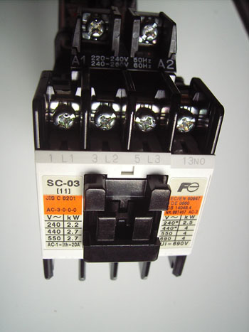
Contactor Layout and Terminals for Field Wiring
 PDF
File
PDF
File
Contactor Layout and Terminals -Photo Identification
PDF
File
Thermal Overload Layout and Terminals -Photo Identification
PDF
File
Single Phase DOL (Direct On Line) Starting
PDF
File
Three Phase DOL (Direct On Line) Starting
PDF
File
The Main contactor of DOL Starters has three NO contacts and one NO and NC Auxiliary contacts. A thermal overload relay is shown in the example but one can use only a contactor without the overload unit. If a thermal overload unit is used, it's rating should correspond to the motor running amperage.
Install the 415 V coil contactor in a suitable enclosure and fix the On/Off Push Button switches at the required operating point.
Wire from a 3 Phase power supply of a 3 Pole MCB or a Main switch of the Power Distribution to the L1,L2 and L3 terminals of the contactor. If a Thermal overload is connected to the contactor's T1,T2 and T3 terminals, then connect the load wires to the motor to the T1,T2 and T3 terminals of the thermal overload.
Now for the control wiring.
Connect a wire to L1 terminal and connect the other end to a terminal of the On Push Button.
Connect the other terminal of the On Push Butto to the terminal of the Off Push button.
The remaining therminal of the OFF Push button should be wired to one of the Thermal Overload's NC contact terminal.
The other terminal of the Thermal Overload's NC contact should be wired to the coil terminal A1 of the contactor.
[ If a Thermal overload is not used, then the remaining therminal of the OFF Push button should be wired to A1 terminal of the contactor.]
Connect the A2 terminal to L2 terminal of the contactor.
Wire from NO Auxiliary contact terminals of the contactor to On Push Button's Terminals.
Now turn on the contactor's
3 Phase supply.
Pressing the On button briefly energizes and holds the contactor in place
until the Off Push button is pressed.
The Thermal Overload sensor will detect any overload and open the NC contact.
Even if the On Push button is hit, the circuit will not be activated until
it is manually reset.
[ Wiring - for Single Phase DOL Motor starting is almost similar but the coil voltage is 230 V. Please see Single Phase DOL (Direct On Line) Starting PDF File.