Assemble your own Portable Power Analyzer Unit at
a Low Cost
Part-2
An idea about the layout and the
material requirement.
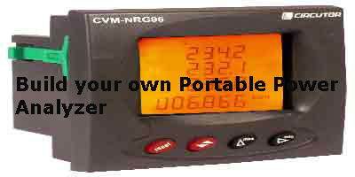
You may be well aware that there are many good quality Panel
Board mount type Power Analyzers [94mm x 94mm size]from many
manufacturers. These meters have a LED or LCD Display for
Electrical parameters such as Voltage, Current,Active Power,Inductive
Power,Capacitive Power, Apparent Power, Power Factor [ cos
pi] ,frequency and Power demand etc.
In addition to have above Electrical parameters displayed,
the models with a communication port can be used to obtain
all data and a graphical display of all parameters from a
PC with a software package provided by the manufacturer of
the Analyzer. This has to be purchased separately but one
can go for a basic package which will not cost you that much.
If you are enthusiased to have the Electrical parameters analyzed
at a later time , it is possible by going for a unit with
a so called Analyzer with a communication port. [ Will be
explained separately with a working model]
The intention of the above description was to make the Panel
Display type Power analyzer the Head or the main component
of the project. Once that was decided, we have to make it
practical to install in a mobile enclosure practical enough
for our purposes. Safety of the user was a main criteria on
deciding the enclosure type. For this purpose, a Metal Powder
coated 300(H) x 250(W) x 125(D) mm [IP 54 / IEC 529 standard]enclosure
was fabricated by a Panel board manufacturer (with required
opening for the 94x94 Analyzer as well as for RS-232/RS-485
Intelligent Converter and field wire connecting sockets)
The author had done his installation projects on PF Correction
Capacitor Banks etc. by using Circutor branded equipment and
components. So the project description here also will be based
on a Circutor branded Power Analyzer , RS-232/RS-485 Intelligent
Converter and Split Core type Current Transformers. The descriptions
and project details given can easily be adopted for Panel
mount Power Analyzer from any other manufacturer.
The other important components are the Current Transformers.
The Handheld analyzers have Clip on type Current Transformers
for their units , which are the most convenient for the easy
handling but the Analyzer we use need somewhat bulky Split
core type Current Transformers. This is somewhat a minus point
in the type of Analyzer system we are going to make [the convenience
vs. cost will always be there].
The author has three sets of Split Core transformers rated
at 100/5A, 500/5A and 1000/5A range but for a starter one
set would be enough, which would be the most used current
measuring range for him. You need three identical split type
CTs [current transformers] for each range to connect to L1,L2
and L3 Phases.
Now we come to the most important thing. That is the Wiring
part of the internal unit and the field wiring part [with
removeable cable links for Voltage [3 Phases and Neutral]
,CT secondary signal lines, Earth connection and Control Suply
for the Portable analyzer Unit.These field wires needs to
be stacked away when not in use and a simple male /female
adaptor system is required for this purpose. The female adopters
need to be fixed to the enclosure which houses the Analyzer
unit.
Copyright 2010 by electrolesk.com
To be Continued to Part-3