
Electrolesk A Guide to Practical Electrical Installation Work.
Electrolesk A Guide to Practical Electrical Installation Work.
Very often the usage of Water Pumps for Water storage becomes a priority where pipe borne water is filled to a storage sump tank and then pumped to a tank at a higher elevation and used with gravity flow for useage.
There should be a large storage tank [ often called the Sump tank built at ground level] which is the water source one need to use to pump to a storage [utilizing tank] tank. Often the storage tank has a lesser capacity than the sump.
The main accessory we need for this project apart from the Water pump and the DOL starter setup, are the float switches.
A float switch is a device which detects two water levels and mechanically switching on and switching off an Micro switch.[ there are also Mercury filled spring loaded sealed tube types with On-Off action - which can also be used ] Some float switche have two floaters operated along a cord.
Another Type which is very simple is a floating water proof [plastic/pvc] device which contains a micro switch inside and a moving weight which activates and deactivates the micro switch and wired with a 3 core pvc water resistant cable of about 2 mt. length.
The Micro switch is a 3 terminal type with a common terminal and a NO and NC type switch.
[ There are electronic type water level detectors but explained here is the mechanical type float switches]
The wiring of the DOL contactor needs to be changed slightly for the Water pump operation.
The method explained in " Wiring DOL Contactor " section is called 'Self Latching' type contactor wiring.
For the water pump operation, it is needed to operate when the float switch is "ON" only and to stop pump operation when the float switch is in "OFF" position.
Sump Tank
One of the conditions for the water pump to work is that there should be water in the sump to a pre defined level.If the water level drops below a certain level, the float switch makes the micro switch to "OFF" position [contact broken]. When the water level reaches a pre defined level above the minimum water level, the float switch makes the micro switch to "ON" position [contact made].
Storage Tank [ Usage tank]
The condition for the pump to activate is, when the water level of the usage tank drops below the defined lower water level.
The other condition for the pump to stop is, when the water level reaches the maximum [upper] water level.
When the water level drops to a pre defined value, the float switch activates the micro switch to the "ON" position [contact made]
When the water level the upper pre defined level, the float switch activates the micro switch to the "OFF" position [contact broken]
1.0 mm2 [called as 1.0 mm squared] Cross sectioned double insulated Cu [Copper] Cables [Cu/PVC/PVC] are used for the Phase [Live ] and the Neutral cables for field wiring
2.5 mm2 [called as 2.5 mm squared] Cross sectioned double insulated Cu [Copper] Cables [Cu/PVC/PVC] are used for the Phase [Live ] and the Neutral cables for Water Pump wiring [ for a 2 HP Motor]
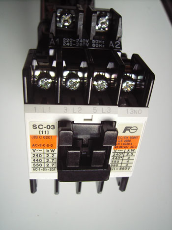
10A Rated Contactor with 3 nos. Normally Open Main Contacts, 1 nos. Normally Open Auxiliary contacts ,230 Volt rated Coil [ 415 V Coil for 3 Ph. Motors]
Thermal Overload unit
DIN rail to mount the above [ normally the relay base or the contactor can be mounted on a din rail]
Float Switches [Micro Switch Type] with 2 floaters- 2 nos
Single Phase DOL (Direct On Line) Starting Water Pump
 PDF
File
PDF
File
Three Phase DOL (Direct On Line) Starting Water Pump
PDF
File
Photos of Micro Switch Type Float Switch
PDF
File
Storage Tank and Float Switch Arrangement
PDF
File
Storage Tank ,Sump Tank and 2 Way Micro Switch operated Float Switch Arrangement
PDF
File - 2 Way Float Switch for Storage Tank
PDF
File - 2 Way Float Switch for Sump Tank
PDF
File - Settingup of Accessories
The Contactor coil should be provided power through the Sump Float switch and the Storage Tank Float switch so that when both switches are "ON", the contactor coil gets energized and if any of the switches are "OFF", the contactor coil de-energizes or drops.
If a Thermal overload unit is used, it can be connected in series with the two float switche.
Here the field wiring will be at two different locations where the Sump and the Storage Tanks are.
Connect a wire to L1 terminal of the contactor and connect the other end to the common terminal of the Sump Tank Float switch.From the NC contact, connect a wire to the Storage Tank Float switch's common terminal.Connect a wire to the NO contact of the float switch and take the other end to the Thermal overload terminal. Now connect the other thermal overload terminal to the A1 terminal of the coil.If the coil is 230 V, then connect the Neutral terminal of the contactor to A2 with another wire. If the coil is 400V , then connect a wire to L2 terminal of the contactor and connect the other end to A2 terminal of the coil.